|
X-150 - A Micro Turbojet Engine Watch me build my engine from scratch !
|
Combustion Chamber |
|
|
Picture |
Description |
 |
The design of combustor is definitely very important for the performance of turbojet. It mixes fuel with air, adding energy by burning, produces combustion gases to drive the turbine wheel downstream. Due to its excessive heat the combustor must be protected by cool air from over-heating. Thermal efficiency is a function of TIT (turbine inlet temperature), the higher the TIT, the better the thermal efficiency. However we must bear in mind that high TIT is not only a friend but also an enemy! as we are using relatively simple technology for protecting the chamber, there's a RED line we should not trespassing. |
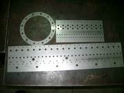 |
Parts for combustion chamber. This is only a trial design, after engine test run we'll be able to see the hot spots and cold spots then we'll decide what to do next. After rolling to shape, each hole will be made countersunk for inducing the compressed air jet into the chamber. Countersunk these holes are tedious work ! To get these parts assembled, the seam is welded by TIG rather than spot due to thickness is suitable for TIG welding. Thinner sheets for example 0.4mm will be advised to use spot welding. |
 |
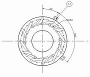
Inner wrapper for combustion chamber. CNC laser cut from 0.8mm thick heat-resistant stainless sheet. The lower end is the front end of the combustor. Why not make a punch die ? Well, maybe after the combustor design is validated, I'll consider this to slash the cost. |
 |
Inner wrapper rolling to shape and seam TIG welded. Side view. |
 |
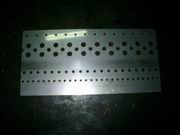
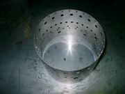
Inner wrapper, bigger holes have been countersunk, smaller holes are waiting to proceed. |
 |
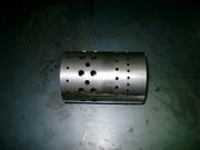
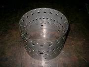
Outer wrapper rolling to shape and seam TIG welded. Top view. |
 |
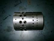
Outer wrapper, holes have been countersunk. |
 |
Swirl jet tubes are welded. No I don't allow those jets to act against any walls, or other tubes ! |
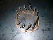 |
Wren type vaporizer tubes (or sticks) are welded on the rear ring of the combustor. Who knows the length of the stick is long enough ? So I chose not to use straight stick, instead I use wren's worm type. Jackson D-sticks will be tried later for performance comparison. The design of vaporizer tubes influence greatly the acceleration and fuel consumption performance of our turbojet engine ! I am so glad that Jackson had decided to put his invention into public domain, so I can have chance to give it a try. |
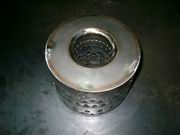 |
The almost completed annular combustor (glow plug bosses not yet welded). |
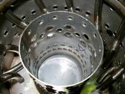 |
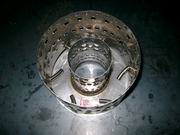
Closer look to the inside of annular combustor, rear end. It looks quite congested inside the chamber, right ? Since this is a trial design, it is prone to be modified to greater of less degree, some of the materials chosen has been downgraded for saving money. When into mass production, best graded 316 as well as seamless tubes will be used. |
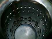 |
Closer look to the inside of annular combustor, front end. |
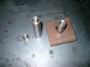 |
Tools, simple punch die is made for countersinking bigger holes. |
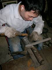 |
This youngster is doing the
countersinking work. As I said, countersunk work is tedious, It must
have been a hard day for him to do this. :-)
Okay, so the combustor is done, next we'll have to work with the mixture of fuel and air to get just the right combination for a good and hot burn. Too little fuel and the mixture doesn't burn hot enough and the resulting thrust is poor. Too much fuel you may be getting enough thrust but the mixture doesn't burn completely, end up a fuel hungry engine. After everything is done right, we'll rebuild the combustor with higher graded materials, such as SUS310 that is very heat-resistant, up to 1100 deg C. Yes, SUS310 is commonly used in burners. |
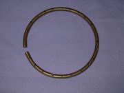 |
Preparing the fuel line for my combustor. When choosing the materials it is reported that brass is more suitable than copper, as copper tends to work harden from subtle vibrations and eventually split causing catastrophe. The Fuel ring, made of brass tube, rolled to shape then drilled along the length 12 holes for inserting smaller manifold tubes. |