X-150 - A Micro Turbojet Engine
Watch me build my engine from scratch !
| Back | Next |
|
X-150 - A Micro Turbojet Engine Watch me build my engine from scratch !
|
Double Plane Dynamic Balancer |
|
Picture |
Description |
 |
No kitting. A serious subproject is born, I am building a dynamic balancer ! Not static balancer, but a genuine dynamic balancer ! Let me explain how a dynamic balancer works. |
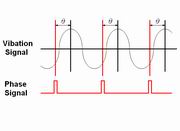 |
How dynamic balancer works. Two signals needed, that is, vibration signal and phase signal. Use accelerometer to pickup the vibration signal. Use optical sensor to pickup the phase signal. |
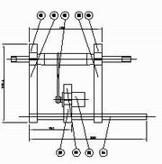 |
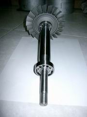
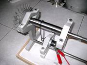
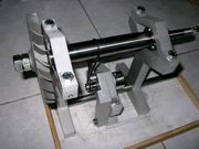
Rotor stand. Belt driven by a DC motor, adjustable bearing stand, quick rotor mounting, etc. |
|
|
Blanking of frame parts. These parts are cut from 20mm thick aluminum plate by CNC water jet cutter, when arranging the layout, make sure that the material waste is at minimum level. Waterjet is perfect cutting tool for handling thick plates. |
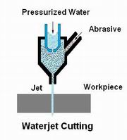 |
Water is soft, but highly pressurized
water can be hard enough for cutting too. There are two types of waterjet cutting
: Pure waterjet cutting: cutting softer material for example cardboard, corrugated board, leather, textiles, cellulose and fibre plastics. Abrasive waterjet cutting: cutting harder materials such as Metals, Glass, Stone, Tiles, Ceramics, high-Strength and difficult to cut alloys, Composite materials and Organic materials. |
|
|
After blanking by water jet cutter.
The leftover is Still usable. There are some small parts can be cut from
it. If you have no idea of what waterjet cutting looks like, well, here it
is the video clip :
|
 |
Almost ready to test. Click on the
following items to see the video clips of balancer test run.
1. Motor driven |
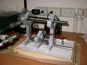 |
All wired up. Two sensors are secured, a WR accelerometer for picking up the vibration signal and optical sensor for phase signal. |
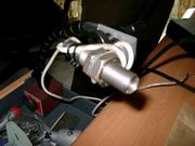 |
Closer look at the optical sensor. |
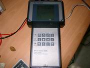 |
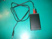
The balance analyzer, produced by a Taiwanese company. This product is an old version, has been phased out for quite a while, the vendor said they have many other newer analyzers, which is stable and precise and cheap. This one is for their internal use only. Later we'll use more advanced software based analyzer. Any PC can do the job very well. |
 |
Tension adjustor at work. There is no need for this part when the belt is new, however the belt tends to lose some tension after a period of time of using, and a tension adjustor could eliminate the problem completely. Basically our first try is successful, next step is to test the repeatability through balancing different turbines. |
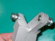 |
Closer look at two tension adjustors. I build several pieces at a time for other balancer's use. Please note that one adjustor is just about for lifetime use, as I care about the quality very much, even such small shaft two ball bearings are used to ensure a very long service life of this part. Pulley is made of aluminum and secured by setscrew. |
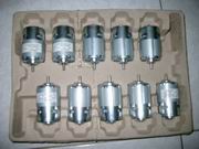 |
These are my stocking motors, can be used for building many balancers ! |
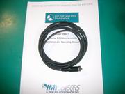 |
My pcb accelerometer. I got this sensor
from PCB's distributor in Taiwan. PCB manufactures high quality
accelerometers.
With the help of my Hungarian friend Miklos, who is good at electronics and developed a series of balancer software. With his help I am able to proceed my balancer project. He uses speaker to pickup velocity signal, I asked him to add accelerometer interface for me. |
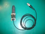 |
The optical sensor. We will use this to pick up the phase signal. |
 |
Signals from accelerometer and optical sensor are integrated at this ICP interface and send into the computer. |
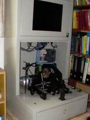 |
This is my new balancer, just arrived,
costs a lot of money, so ripped a big hole on my wallet. It is not tailor
made for me, I need to modify this machine so that it perfectly meet my
requirements on the rotor balancing.
I previously out-sourced the balancing work to balancing service companies, the results were good but was also very time consuming. From now on, I have my own machine so I will use this balancer to do rotor balancing. Accuracy : ISO1940 G2.5 or better. The machine weighs more than 100kgs. I find a nice corner in my office to place this machine. I will show some results if I have time. |
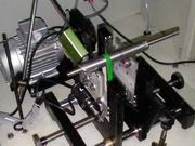 |
These are the modifications on the machine. The support is my own design so that the shaft mounting can be adjusted in two directions to remove axial movement. The belt drive is also modified to have higher contact angle so that the shaft can rotate at higher speed. |
 |
Jetbeetle's developing its own
balancing machine ! This is what the software interface of ARX dynamic
balancer looks like. After 2
months of hard work finally I got it working ! This is very exciting. When
adding trial weight on the planes, the machine could really sense the
existence of unbalance and show it correctly . This is a proof of machine
validity. The machine uses wattmetric filtering technology to remove any noise generated by the machine so that only signals from the rotating workpiece is processed. History plot of our ARX balancer is easy. We could record the balancing process and display the history of balancing. If you want to see a specific no. of measurement, just drag the slider up and down and you got it. History plot is very useful, it could not only provide the final balance result, it could also be used to show the performance of a balance procedure. If the unbalance amounts are converging all the way down to zero, the balancing job is done very well.
Click on picture to see a bigger one. |
 |
Jetbeetle's state of the art noise
filtering technology. Sometimes we get data with more noise than signal, or
the signal noise ratio SNR is lower than one. We could design a very good
bearing mechanism so that SNR is greater than one. But very noisy
environment could happen.
This picture shows two history plots. It compares two tests each showing 10 measurements. The unbalance is approximately 1000mg, located at 0 degree, 10mm radius. On the right -- just using ordinary wattmetric filtering. The result is good but data kind of scattering. On the left -- wattmetric filtering + Jetbeetle's special filtering technology. The data shows extreme concentration and consistency. Click on picture to see a bigger one.
|