X-150 - A Micro Turbojet Engine
Watch me build my engine from scratch !
| Back | Next |
|
X-150 - A Micro Turbojet Engine Watch me build my engine from scratch !
|
Compressor and Intake |
|
Picture |
Description |
 |
The compressor draws air into the engine, pressurizes it, and delivers it to the combustion chamber. It is driven from the turbine by a shaft. There are two types of compressor: the centrifugal flow impeller type, as used in our engine, and the axial flow type which has several stages of alternate rotating and stationary aerofoil blades. Multi-staged axial compressors can achieve compression ratios in excess of 40:1. |
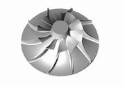 |
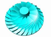
Modeling the driver blades. The blade is retro-curved, not so easy to get it done by hand. So I devised a mystery equation for calculating the characteristic curve. Fortunately this 3D CAD allows user to do some customization by user program (and thank god I know how to do it). So many trial characteristic curves can be created by my program simply by adjusting parameters, then we can chose among them to get the best one I need. So sweat once (the programming approach) instead of sweat many times (the manual approach). |
 |
Closer look of the blades. I
never get tired watching at them. Next, we need to add divider blades... Good news : divider blade is similar to driver blade, so it can be made conveniently by copying and trimming ! |
|
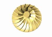
Completed 3D CAD model.
Note that the blades are of retro-curved type, so theoretically we'll have smooth
and quick throttle performance. It has relatively small trim so we're expecting to
obtain high pressure ratio. Diameter of this wheel : 130mm.
PS. Trim = (Inducer Diameter)2
/ (Exducer Diameter)2 x 100 |
 |
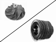
This is a wheel with radial tipped
blades I bought from eBay. No retro-curved blades, no maker, no
compressor map, no nothing. Yet it has one advantage after all : it is
ready-made, pre-balanced and pre-bored, can be used right away. So for
convenience it is a substitute for my own designed wheel.
PS. Thanks to the eBayer who sold me the wheel, he informed me the wheel should be from Cummins VT or ST-50, they use the same wheel. |
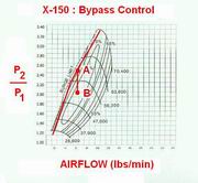 |
The idea of adding bypass control to
the discharge side of compressor, to prevent compressor surging, hoping that
the bearing failure caused by compressor surging can be eliminated
completely. Don't tell me this has been done already !
The state of a compressor represented by coordinate (airflow,p2/p1) should never trespass the long red curve indicated as the bypass curve. Once touched (point A), the bypass valve opens, venting some pressure off to the atmosphere (point B), so p2/p1 drops and surging is avoided. |
 |
Compressor candidates of extreme cases. On the right, a high mass flow compressor, left, a high PR compressor. I am going to find out through experiments what trim size is perfect for my engine. |
 |
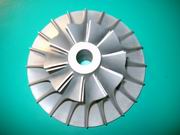
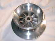
Unveiling Jetbeetle's new compressor
PR5 design. Yes, it can deliver pressure ratio up to 5.0. This wheel features bigger trim size, a merged axial stage,
and retro-curved blades, 12 main blades 12 splitter blades, total of
24 blades, all aiming at better air throughput and
compression ratio, in addition, smoother throttle performance. I am considering to cast this impeller in
Titanium. Guess what trim size I am using.
|
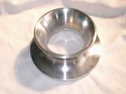 |
Intake. CNC turning completed. |
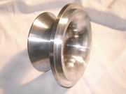 |
Another view of this Intake. It will be sent to next stop for drilling. |
 |
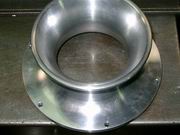
Try fitting with the VT50 compressor. It fits perfectly ! What do you think, does it need to be anodized for some coloring ? |
 |
6 holes are drilled for securing the intake to the front cover. Slightly bigger holes are needed to cope with position deviations from the matching threaded holes. |
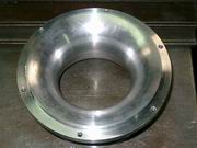 |
Intake holes are drilled. Viewed from the bottom. |